CAM Software Speeds Up Prototyping and Manufacturing

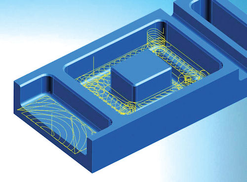
OPEN MIND’s hyperMAXX high-performance cutting module, which is fully integrated into hyperMILL.
Rapid Prototyping and Manufacturing Services News
Rapid Prototyping and Manufacturing Services Resources


Latest News
March 29, 2014
 OPEN MIND’s hyperMAXX high-performance cutting module, which is fully integrated into hyperMILL.
When it comes to prototyping and manufacturing parts via subtractive technologies, as opposed to the additive manufacturing (AM) methods used by 3D printing, speed is the name of the game. Sending the right tool for the job and material along the most efficient path is a key feature of computer-aided manufacturing (CAM) software.
For example, SolidCAM trumpets its iMachining milling technology as saving “70% or more in CNC (computer numerical control) machining time.” In Mastercam X7 from CNC Software, Inc., users can select an Optimize cut order checkbox that “reduces unnecessary motion and shortens the length of the toolpath,” according to a blog post from the company. PTC Creo Complete Machining Extension “enables you to directly machine simple or complex product geometries with NC toolpaths optimized for manufacturing lines,” according to the company. And Siemens says its NX CAM feature-based machining technology can reduce programming time by as much as 90%.
“Today, toolpath efficiencies are often inherent in the CAM software, but are different between different brands of software,” says Alan Levine, managing director at OPEN MIND Technologies, which develops hyperMILL CAM software. “Users may have many buttons to control aspects of the toolpath process such as start points, transition air moves, feed-rate control and more. But high-performing systems will achieve optimization ‘out of the box’ and often not require much tweaking by the CAM programmer. Many CAM software have fundamental differences in how they manage trimming toolpaths to stock conditions.”
Efficient Doesn’t Mean Dumbed Down
With such out-of-the-box functionality of standalone CAM software, and the availability of CAM plug-ins for popular CAD packages—including Dassault Systemes’ SolidWorks and Autodesk’s Inventor—can CAD experts become CAM experts by checking the right boxes? Not necessarily.
“There are things outside just the cutter path that yield the best results and an experienced machinist will always be able to dial in a strategy just a little more to fit it to their tastes,” says CNC Software’s Marketing Coordinator Michelle Nemeth. “A benefit of good CAM software is that those machinists can save those preferences to a library for future use—passing on their experience to newer machinists.”
Levine agrees that experienced CAM users generally have a strategy in mind, and then make selections within CAM software to meet their needs given a particular cutting scenario. They take variables such as machine tools, holder systems, cutters, material, quality specification and more into account—factors that inexperienced CAM users may overlook.
“This is especially true for applications with harder materials, or parts requiring small cutter sizes or higher precision, where deeper knowledge of manufacturing techniques must be included in the programming process to obtain the intended results,” Levine says.
He notes that users may have different definitions of optimal machining. Some may want to reduce cutting times; others may want higher quality output—and still others may value reduced wear and tear on the tool and machine above all else. For these reasons, it is difficult to optimize CAM software for everyone out of the box.
Integration Grows Deeper
Just like the traditional design, simulate, prototype, test, manufacture model has been revolutionized by the widespread acceptance of simulation-led design and rapid prototyping technologies, the relationship between CAD and CAM is getting closer. As a whole, the design-build cycle is becoming more collaborative and integrated, as technologies overlap and break down traditional job descriptions.
In what may be a sign of things to come, Autodesk, known for its design software, has made a number of acquisitions in the CAM market—namely HSMWorks in 2012 and Delcam earlier this year. (Editor’s Note: For more information on Autodesk’s CAM moves, see “CAM Heads to the Cloud” by Kenneth Wong, March 2014.)
“Integrating CAM with CAD has many benefits and has become very popular in recent years,” says Levine. “The primary efficiency is revealed by sharing the same model database between design and manufacturing tasks, without translating through neutral file formats or possibly reverse-engineered interfaces.”
On the flip side, “having CAM tied to the CAD software means a single seat of software is tying up both those tools,” notes Nemeth. “It also can pose a challenge if the shop either uses different CAD packages or needs to machine CAD files from different sources,” she says.
Integrated with CAD or standalone, a design engineer who understands the repercussions of design modifications before they’re made can save time down the line. One way to do that is by simulating the toolpaths required to create the part. Software like Spring Technologies’ NCSIMUL Machine can not only verify and validate CNC coding, but can help design engineers review and optimize their designs based on the characteristics of the particular machines being used to prototype and/or manufacture the parts they are designing. Design engineers can reduce engineering change orders coming from the factory floor—and CAM programming times—by making sure their designs are capable of being milled in an efficient manner.
As the lines between CAD, CAM and simulation continue to blur, CAD users new to CAM shouldn’t be intimidated by what may at first appear to be a steep learning curve.
“Any CAD experience will translate into a shorter learning curve for the CAM user,” says Nemeth. “Just understanding how geometry is defined and what is available for editing geometry will make the learning curve flatter.”
More Info
Subscribe to our FREE magazine, FREE email newsletters or both!
Latest News
About the Author
Jamie Gooch is the former editorial director of Digital Engineering.
Follow DE


